On the class homepage, I described self-assembly as being "when we design the parts so that they know how we want them to finally come together."
This is loosely correct, but it trivializes self-assembly by implying that once the parts are correctly designed and built, all we have to do is get out of the way. Nature is seldom, if ever, so accommodating. Real-world self-assembly will almost always produce many, many alternative structures. If we did our design work properly, the structure we intended has the lowest energy of these alternatives. But that does not mean that nature will home right in on this structure. Instead, via a statistical process, nature will sample all of the structures, assembling them and disassembling them. Or, even worse, it will assemble part of one structure here, and part of another structure over there. Nevertheless, under just the right conditions of temperature and reactant concentrations, our desired lowest energy configuration will be slightly more robust, and will stay together slightly longer. Then, over time, it is likely that more and more of our reactants will find their way into the configuration we intended.
This delicate balance of assembly and disassembly is at the heart of all self-assembly processes, ranging from crystal growth to protein folding. And as one who spent a career trying to optimize various forms of nanoscale self-assembly, I felt that it was essential that any student lab on self-assembly not only include this balance but that it do so in a way that was clearly visible to the students. This belief led me away from lab ideas such as chemical synthesis of gold nanoparticles (as depicted in the materials for my The Need for Self-Assembly lecture note set) because you cannot really see what is happening in chemical synthesis and must accept the suggested self-assembly mechanisms on faith.
I therefore looked for macroscopic models that would clearly depict the balances of self-assembly. The best I ultimately found were created by the educational outreach team from the University of Wisconsin's former NSF MRSEC center. They developed floating magnetized shapes that served as analogs of self-assembling atoms. The links to their work are now disappearing, so I have cached the key webpage HERE. Its movie shows magnetized triangles of blue and green gradually coalescing into an alternating structure:
To me the Wisconsin work provides a wonderful example of realistically complex self-assembly. However, it did this with considerable realism in that in the unedited movie it took over eight minutes for the pieces to complete only partial self-assembly. A student-friendly lab would have to accelerate self-assembly without sacrificing realism.
I was eventually able to track down the developers of the Wisconsin demonstration: Karen Nordell and George Lisensky (both now at Hope College). Karen told me that their very regular water agitation was produced by an "orbital shaker." But she also told me that their shapes were specially made by formulating resins impregnated with magnetic particles, baking these resins within custom molds incorporating permanent magnets, and then slicing up the resulting bars. For my class labs I wanted a simpler process. And this seemed to suggest starting with prefabricated floating shapes.
Preliminary Attempt using Cuisinaire Pattern Blocks:
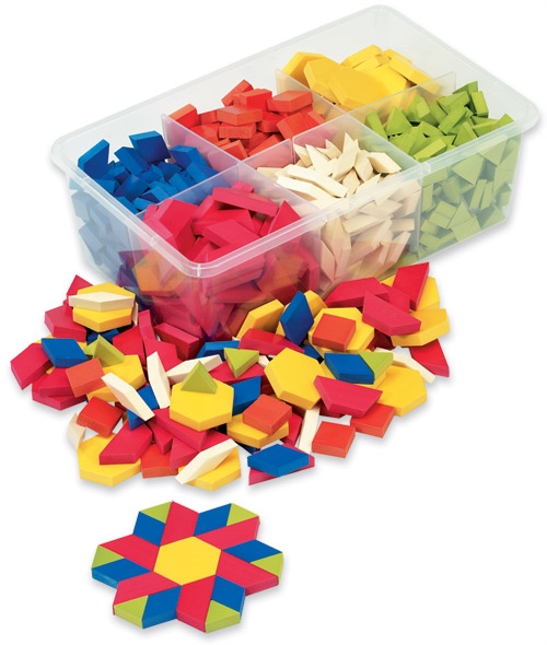
I found a promising set of such shapes manufactured by ETA Cuisinaire / hand2mind (www.etacuisenaire.com) at both their website and through educational supply stores/websites. These shapes are available in either wood, foam rubber, and hollow plastic. I chose the hollow plastic set (P/N 4414) both for its compatibility with water and because it would allow for the most precise positioning of magnets (which proved to be crucial).
I next went to Indigo Instruments (www.indigoinstruments.com) which has an exceptionally broad selection of small magnets. There I bought small cylindrical rare earth magnets of various sizes (diameters of 3-5 mm, thicknesses from 1-2.5 mm). Into the faces of different triangular blocks I drilled holes of each magnet diameter and pressed in one magnet per face (with north poles out in certain blocks and south poles out in other blocks). When I then floated the shapes in the orbital shaker, attempting to emulate the Wisconsin movie, all of the blocks coalesced violently, even those with the smallest magnets (3 mm diameter x 1 mm thickness). And with even the strongest possible shaker agitation (splashing water out of the bath and on to the lab bench) the shapes would not come back apart.
Because I could not find any smaller or weaker magnets (and indeed smaller magnets would have been very difficult to handle), I looked into ways of embedding the magnets deeper into the shapes such that even when the faces of two blocks came together, the magnets would remain some distance apart. Online I found various short plastic tubes with inside diameters that almost perfectly accommodated Indigo's smallest 3 mm diameter (by 1mm thick) magnets. These tubes came in various lengths running from 3 to 8 mm. I bought an assortment of lengths, and then super glued single magnets at one end of the tube. I then drilled holes in the center of the faces of the Cuisinaire shapes big enough to accept the tube/magnet assemblies, and then super glued them in place (with the magnets now offset into the shapes).
When I tested the shapes with different length tubes I found that to get get a realistic balance of assembly AND disassembly, I had to use the tubes that set the magnet faces 4 mm back from the shape faces (i.e. 5 mm long tubes). This meant that to get behavior analogous to atomic self-assembly, even these tiny 3 mm diameter magnets could not be allowed to come closer than 8 mm to one another!
However, these shapes still had two pronounced deficiencies:
- Water surface tension between the flat faces of two Cuisinaire blocks could bind them together more strongly then the magnets (or even in the absence of magnets).
- Self-assembly still demanded a LOT of patience and time (more than I expected my students to have).
This suggested two solutions:
- To overcome water tension binding, either use shapes with bumped or crowned edges (that would minimize contact area) OR shapes with faces that could come together tightly only on the desired faces (by use of complex curves).
- Start with unrealistically easy self-assembly and then gradually add real-life complexity. Specifically, start with shapes that could ONLY come together in the single desired manner. Then move to slightly imperfect shapes where binding is more tenuous. And only then move to shapes that could come together in more than one configuration (as in nature).
But to add those degrees of freedom, I had to move to custom shapes. Fortunately it was as that point that I learned of UVA's new 3D printing facility.
3D Printed Shapes:
The UVA "Rapid Prototyping Lab" is housed in the Mechanical Engineering Department and uses a variety of 3D plastic printers. It is open to all comers (UVA and non-UVA) and implements designs based on "STL" format 3D CAD files. The printed shapes are priced based on the weight of plastic each incorporated, and the charge (the same for both internal UVA and external credit card charging customers) for the full shapes below averaged about one dollar apiece.
To design our custom 3D self assembly shapes, on advice of the Rapid Prototyping Lab, I initially downloaded Autodesk's Inventor program (free to students and teachers). While I found this program to be hugely capable, I also found it very hard to learn (especially before also purchasing its companion Autodesk book - this for someone who has spent 15 years authoring 3d animated content for the "UVA Virtual Lab" science education website). Inventor (along with its almost dozen co-installed helper programs) was also huge, glacially slow to load, and could be counted upon to crash at least once during loading (this on a one year old high performance laptop). Further, Inventor is only compatible with Windows PCs.
Nevertheless, a TA trained on Inventor and I did manage to design the initial generation of shapes described below. More recently, however, I discovered a much, much easier to use alternative: Bonzai3d. This program also offers free versions for students and faculty, but has an intuitive and efficient user interface, and loads quickly on both PC and Mac computers. Indeed, I mastered it in one morning after viewing a couple of the dozens of tutorial videos posted on the Bonzai3d website. The shape files provided below have thus all now been reworked into Bonzai3d files (and their STL exports).
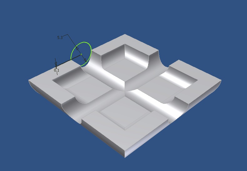
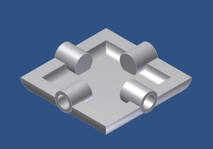
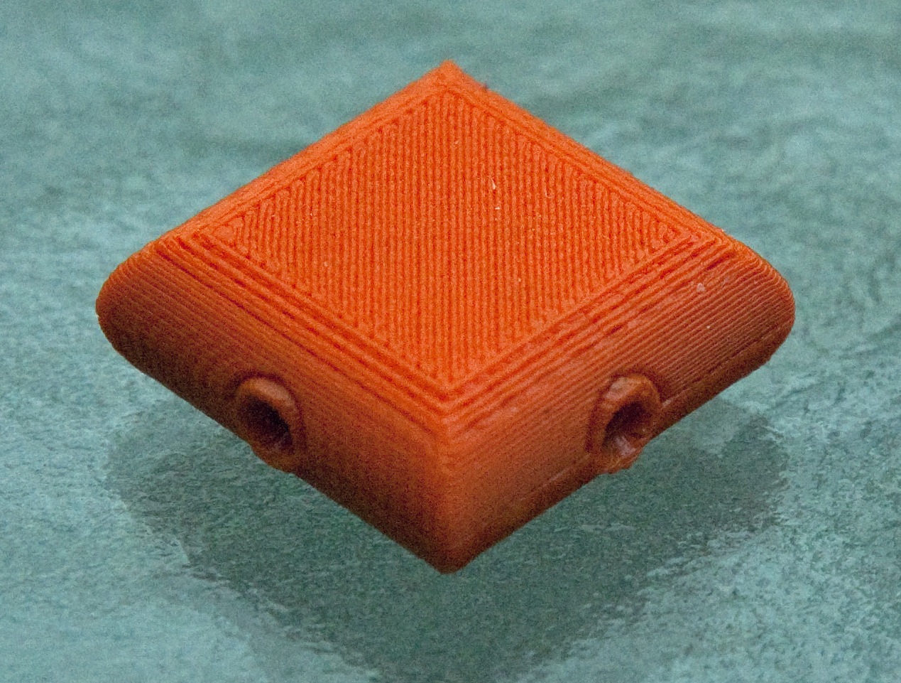
Using these programs, we designed thin wall hollow plastic shapes (similar to Cuisinaire's). These shapes would be formed by gluing together top and bottom half shells (with the faces of all shapes exactly 2 cm long). But, as custom designs, I was able to make the side faces of many of my shapes half cylindrical (thereby minimizing their ultimate contact area). Further, I could do away with the tubes above, and instead design into the bottom half shells the necessary dead-ended cylindrical magnet-mounting holes. However, because the 3D printing process produces slightly rough surfaces, I had to allow larger than normal tolerances to achieve tight fits (e.g. 0.1 to 0.2 mm, determined via printing of trial shapes). I also doubled the wall thickness of larger square shapes so that they would float at the same level as the smaller shapes. Below are CAD images of the half shapes, along with photographs of the fully assembled 3D printed plastic units.
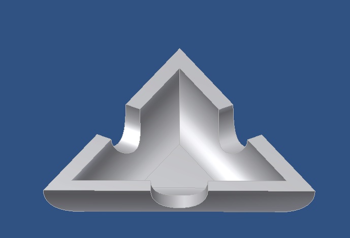
Triangular shape - Top
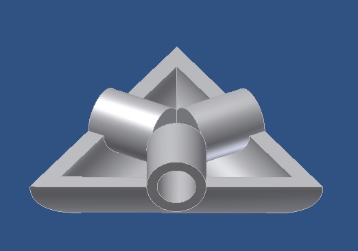
Triangular shape - Bottom
Square shape - Top
Square shape - Bottom:
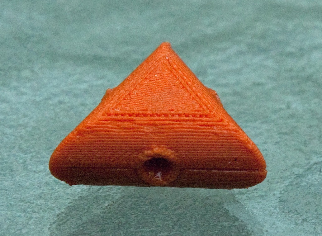
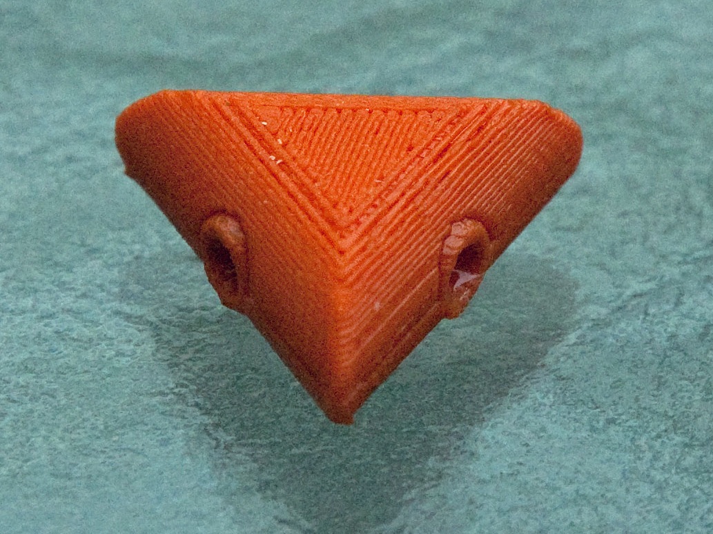
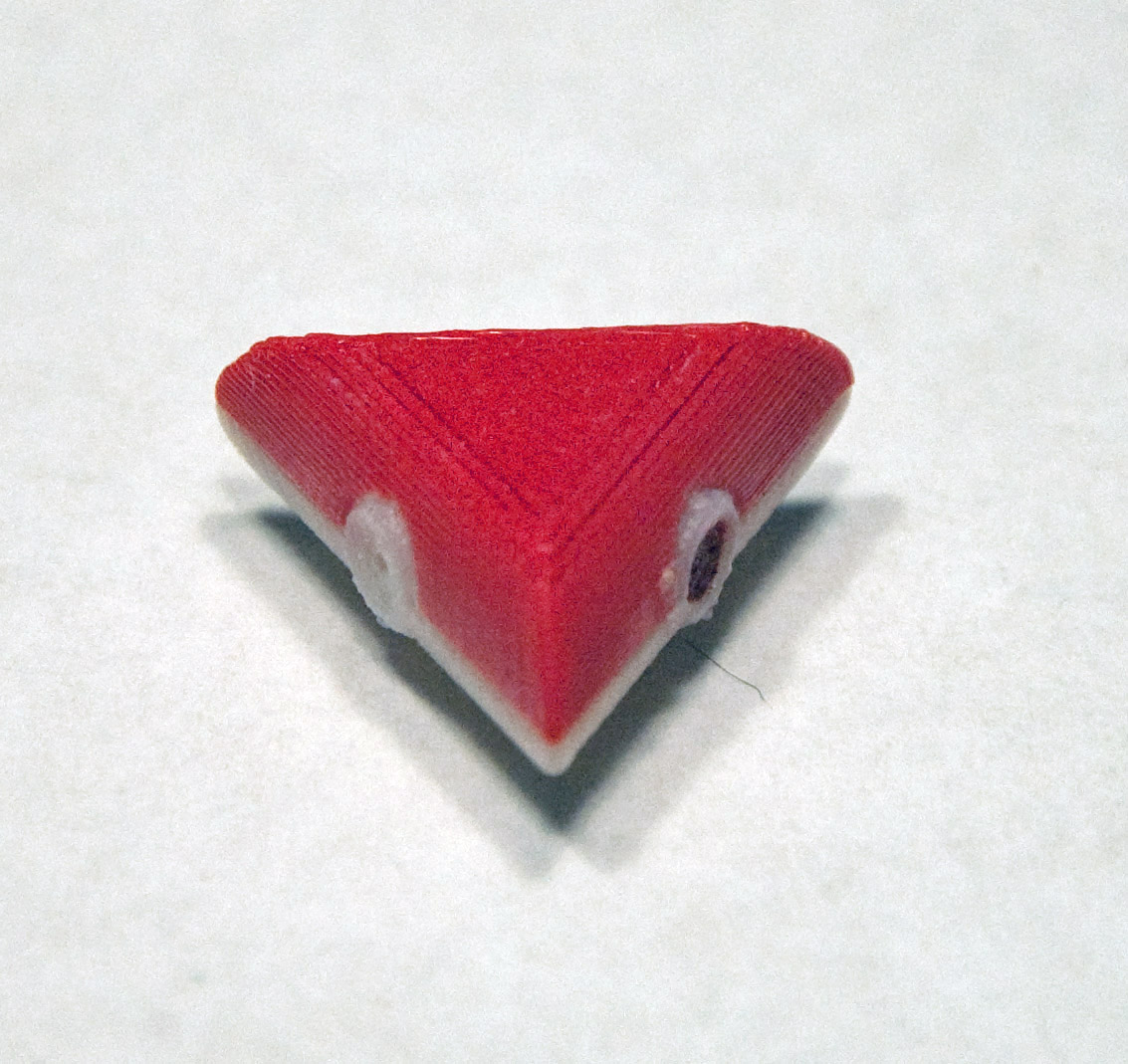
Printed and assembled ABS plastic triangular shapes
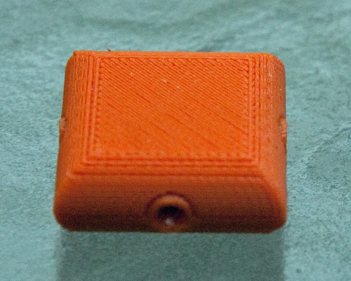
Printed and assembled ABS plastic square shapes
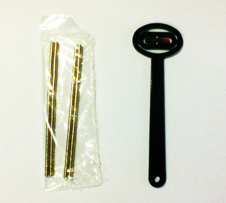
Once the 3D printed pieces were received, 3 mm diameter by 1 mm thick magnets were super glued (cyanoacrylic) as desired into the blind holes in the bottom pieces of each shape. To determine the orientation of the magnets, a "Magnaprobe" was also ordered from Indigo (shown below). The quickest way to mount magnets was to use the probe to first determine the orientation of a stack of magnets, and to then slide off one magnet at a time on to the head of a 4d finish nail (which has a diameter slightly smaller than 3 mm). The attached magnet was then dipped in a shallow puddle of super glue, then inserted all the way into the shape's hole. Note that, especially with the triangular shapes, the inward facing magnet poles of the magnets strongly repel one another and it is necessary to hold the magnets in place for many seconds to ensure they do not pop back out or flip within the hole (rotating the nail during this process so that the excess glue does not attach the magnet to the nail). Finally, red, blue or white RTV silicone glue was squirted into the holes to protect the magnets, eliminate the bubbles the holes would otherwise hold, and to label the individual magnet orientations (I used red for inward facing north poles, blue for inward facing south poles, and white for holes with no magnets). Once the RTV had set up (24 hrs), top and bottom shape pieces were fitted together and super glue applied to the seam. This is easier if one buys low viscosity super glue with a narrow applicator tip - as sold by hobby stores or websites. Because the 3D printed shapes are somewhat rough, seams may be wide enough that a second application is necessary to ensure water tightness.
Photo of 3 mm diameter magnets (in stacks of 50) and Magnaprobe magnetization sensor purchased from Indigo Instruments (www.indigoinstruments.com)
ORBITAL SHAKERS AND BATHS:
For simpler demonstrations, water baths may just be agitated by hand. But to systematically explore subtle self-assembly effects (as done in the experiments below), the exact degree of agitation must be very well controlled. The degree of agitation reproduces the effect of temperature (i.e., Brownian motion) upon nanoscopic nano shapes and atoms.
For our experiments (listed below) we follow Wisconsin's lead by floating shapes in a water bath placed upon an "orbital shaker." Orbital shakers are actually slowly gyrating tables. It is important to obtain units with large tables and low adjustable rotation speeds. Our units have a 12 x 14 inch table and a speed range of 3-70 RPM. (NOTE: these units cost between 200 and 300 dollars apiece, radically increasing the overall cost of this lab - suggestions on alternatives would be most welcome!).
Our orbital shaker's 3-70 RPM speed range was set by a 3/4 turn 86 k-Ohm potentiometer. But only the lower half of that range allowed for self-assembly of our shapes. This limited range of adjustment (~ 3/8 turn) made it very difficult for students to observe the extreme influence of vibrational energy (i.e., temperature) upon self-assembly. We therefore replaced this potentiometer with the parallel combination of a fixed 1 Mega-Ohm resistor and a 10 turn wirewound 100 k-Ohm potentiometer (yielding a near matching 91 k-Ohm load resistance). To the potentiometer we further added a counter dial. These replacement parts are given in the "General Materials" table below (but should be substituted only if your unit comes with a near 90 k-Ohm value potentiometer, and with the knowledge that this substitution will probably void the unit's warranty).
BATHS: For the bath container itself, square baths produce large disruptive waves at their corners, making round shapes preferable. For a round shape that almost fills the above shaker table, inexpensive 12" diameter "pie carriers" were purchased from retailer "Bed, Bath & Beyond."
FINAL TWEAK: Water surface tension can lock the floating shapes up against the smooth inner walls of the bath (even after a drop of detergent is added). To overcome this problem, the inner walls of the baths were "roughened" by lining them with bands cut from a ribbed rubber floor mat bought from Mc Master Carr.
GENERAL MATERIALS
Material and shape quantities given are for labs of 9 students, divided into three teams:
Material
Qty.
Material
Qty.
Indigoinstruments.com 3 mm dia. x 1 mm thk. Nd magnets, SKU43511
300
Variable Speed Orbital Shaker
3
indigoinstruments.com Magnaprobe Mark II, SKU 44702
1
Allied Electronics 10 turn 100k pot, P/N 70153715
3
Cyanoacrylic glue - low viscosity - small applicator tip
1
Allied Electronics counter dial, P/N 70153350
3
Loctite Superflex Silicone RTV - Red, P/N 59630
1
Allied Electronics 1 M-Ohm resistor, P/N 70200390
3
Loctite Superflex Silicone RTV - Blue, P/N 30560
1
12" dia. "pie carriers" Bed, Bath & Beyond
3
Loctite Superflex Silicone RTV - White, P/N 59430
1
Mc Master Carr rubber mat P/N 6895T711
1
PRINTING OR ORDERING YOUR OWN 3D SHAPES:
The Bonzai3d and STL files for each shape can be downloaded using the links in the figures below. These files will allow you to order your own copies from many 3D printing companies. You can also use the UVA "Rapid Prototyping Lab" that I used, which accepts external credit card billed orders. I was told that you will be charged at a rate identical to what I was charged as a UVA professor. I was also told that this rate was lower than charged by alternate 3D printers, but I have not personally verified this (if you DO identify less expensive printers, please notify me and I will post links to them).
To order shapes from UVA's "Rapid Prototyping Lab" you must first register at:
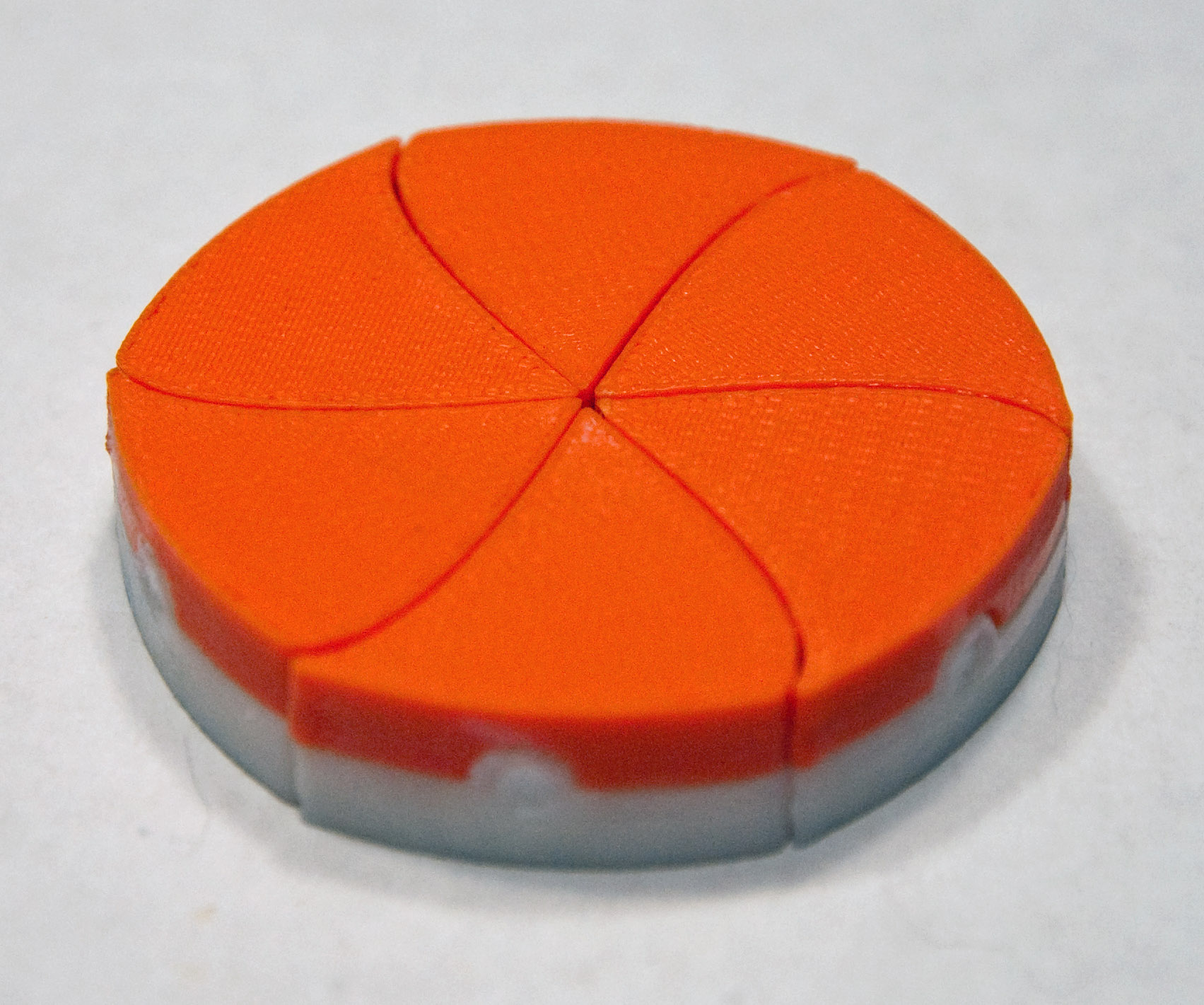
1) Idealized Self-Assembly: Parts that can ONLY come together the way we want them
FOR THIS EXPERIMENT USE: 6 orange/white near triangular "pinwheel" shapes
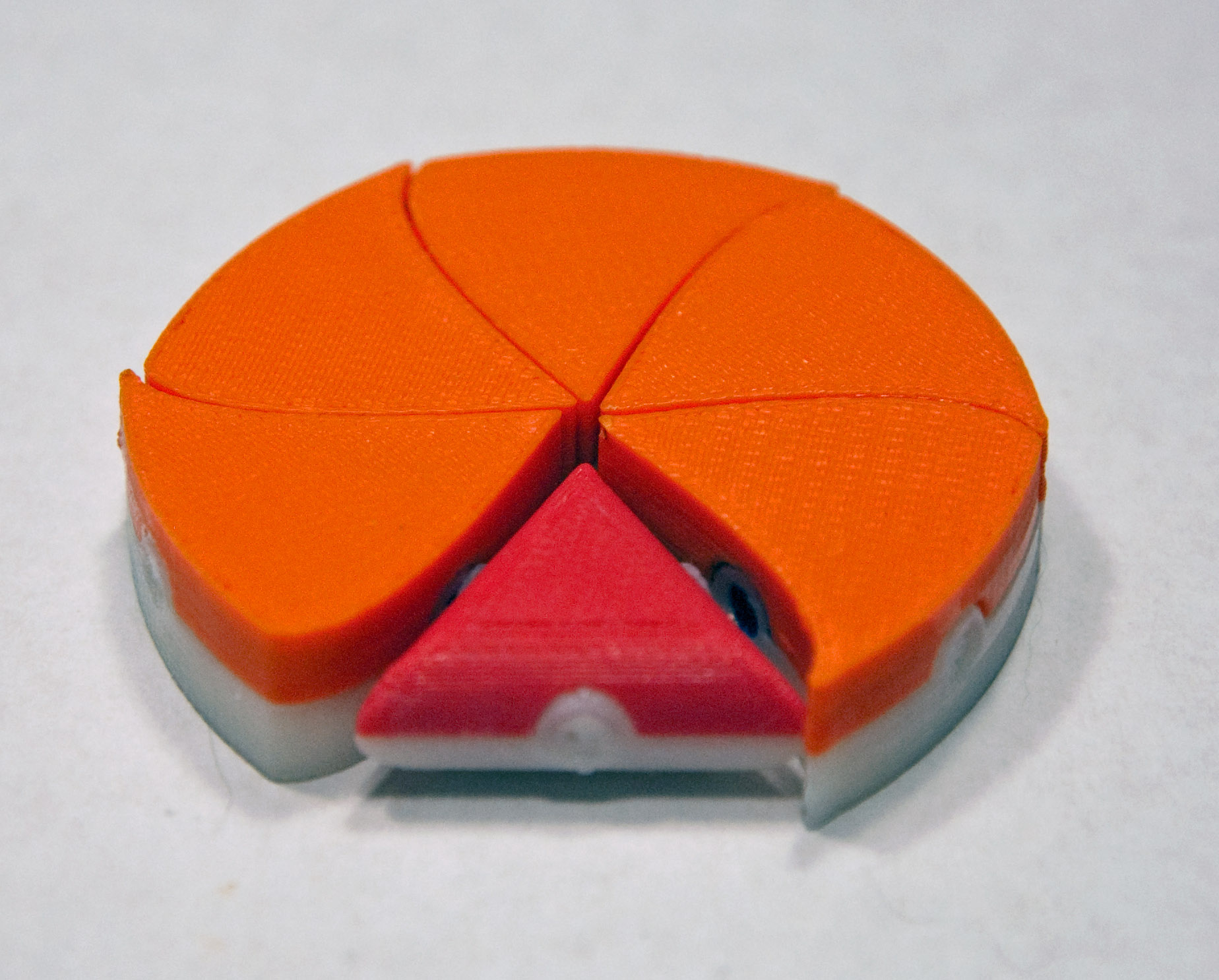
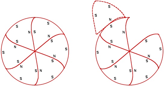
This experiment is run as a timed contest between class teams. The winning team is the first to achieve full self-assembly by controlling only the orbital shaker's rotational speed (temperature). The experiment uses triangular shapes with their faces curved so that they will only fit together tightly in the desired pinwheel shape. Tops of the shapes are orange, bottoms are white (so marked because upside down shapes would not fit together as intended). As shown in the schematic at the far right, magnets are embedded in ONLY in the shape faces that are intended to bond together:
CAD files for pinwheel shape (3D printing colors: top orange / bottom white):
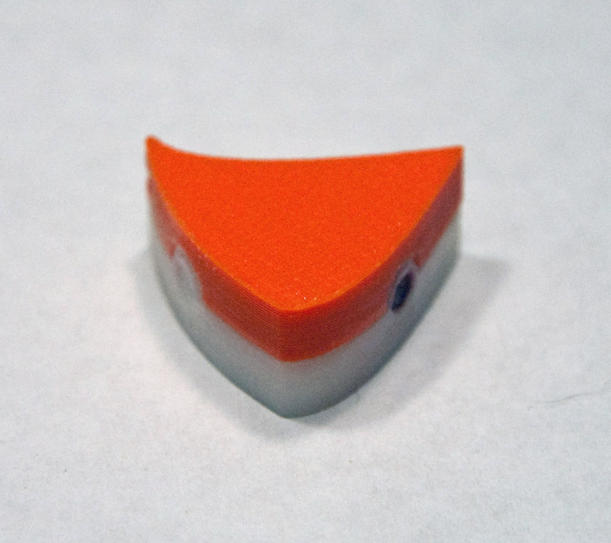
2) Slightly Non-Ideal Self-Assembly: A substitute part with not quite the right shape
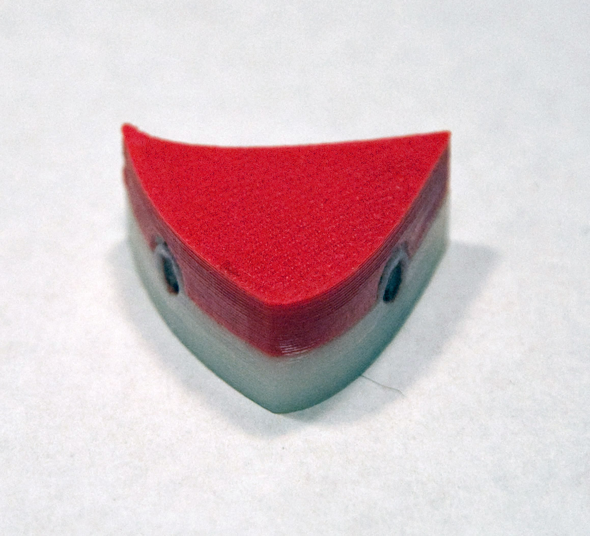
FOR THIS EXPERIMENT USE: 5 orange/white near triangular "pinwheel" shapes + 1 red/white triangle
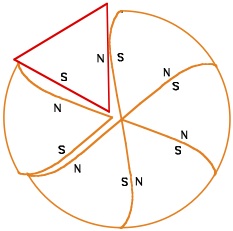
This experiment is again run as a timed contest between class teams. It is a variation on experiment #1 where one of the orange/white shapes is replaced by a triangle with straight sides that won't quite fit into a perfect pinwheel. As shown in the schematic at the far right, all of the shapes (new and old) still have magnets are embedded in ONLY in the shape faces that are intended to bond together:
CAD files for triangle shape (3D printing colors: top red / bottom white):
3) Realistic Self-Assembly: Parts that can fit together in more than one way
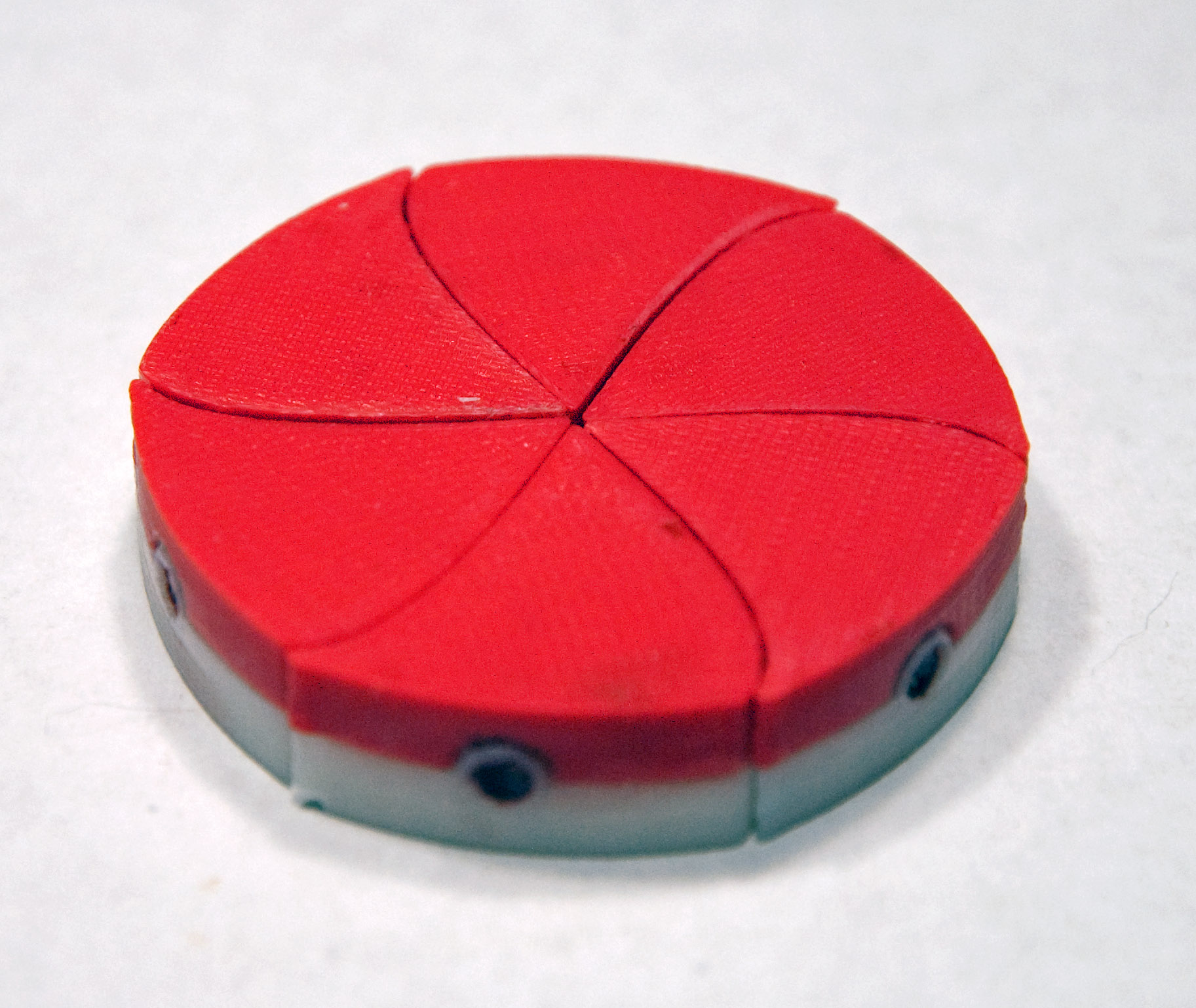
FOR THIS EXPERIMENT USE: 6 red/white near triangular "pinwheel" shapes
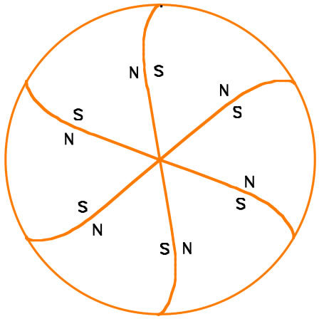
This experiment is again run as a timed contest between class teams. It resembles experiment #1 but each shape now has an added (S) third magnet. As shown in the schematic at the far right, this means that shapes can now come together in two different ways. In the new configuration the curves of the mating faces don't match precisely. As a result, this new bonding will be slightly weaker than the original more tightly fitting configuration. This represents natural self-assembly more realistically in that the "temperature" (orbital shaker speed) will have to be set so that the alternate bonding configuration is broken back up while the original bonding configuration persists.
CAD files for pinwheel shape (same as experiment #1 but 3D printing colors: top red / bottom white):
4) Even more Realistic Self-Assembly: All bonds are equal but final configurations are not
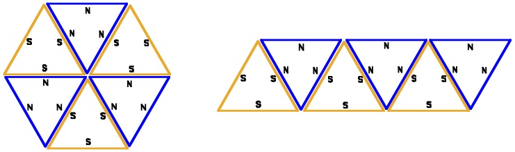
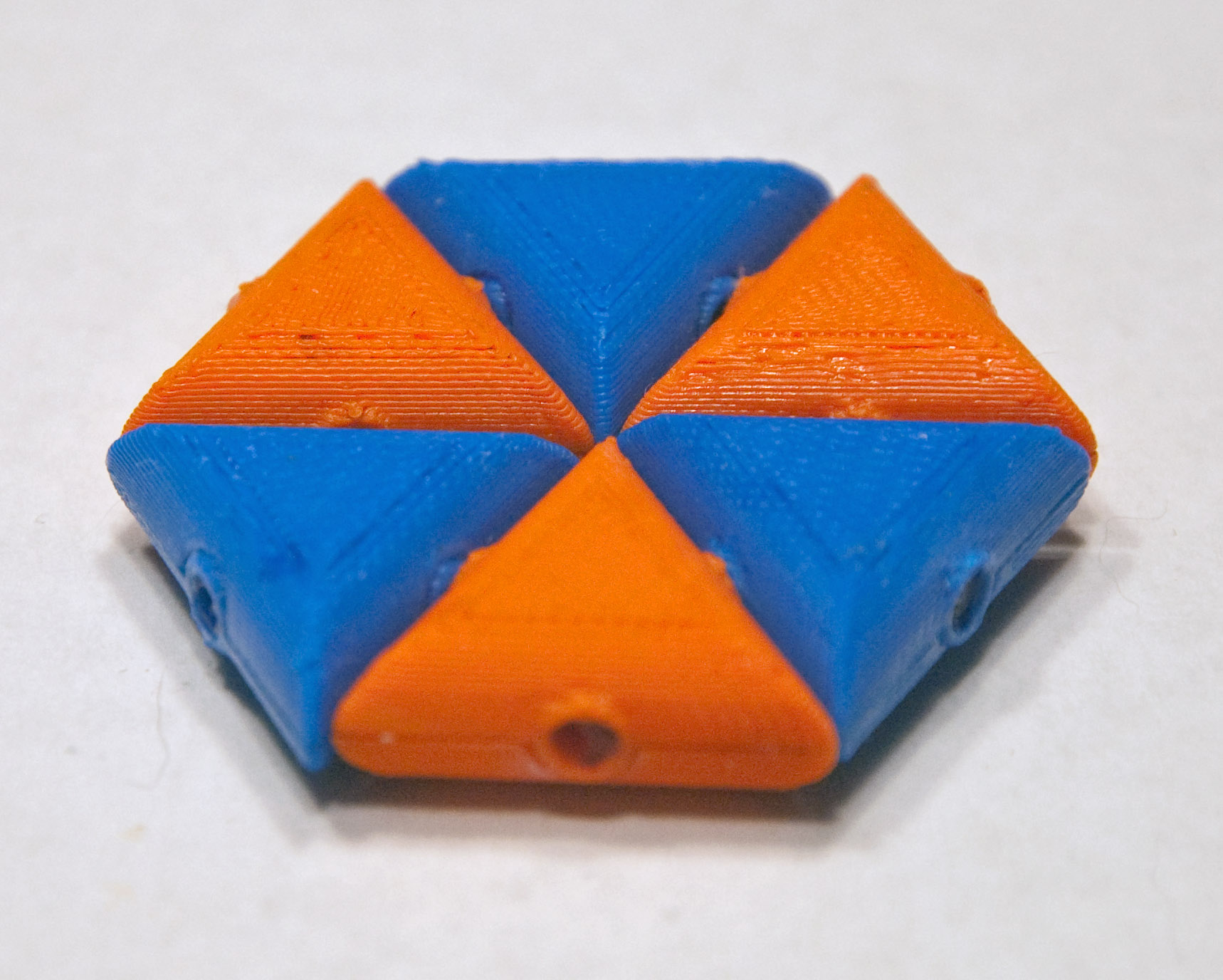
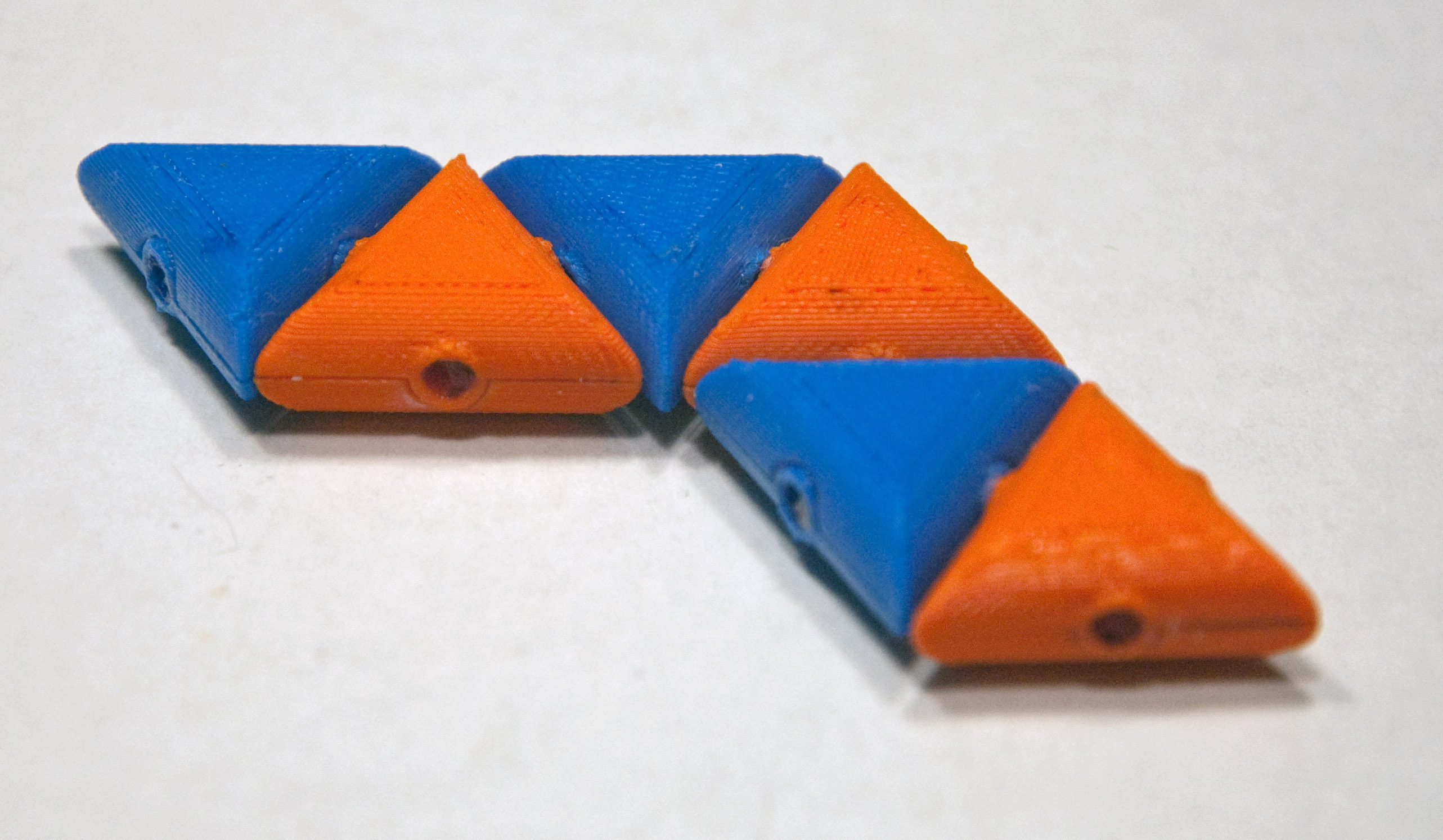
FOR THIS EXPERIMENT USE: 3 solid orange triangles + 3 solid blue triangles
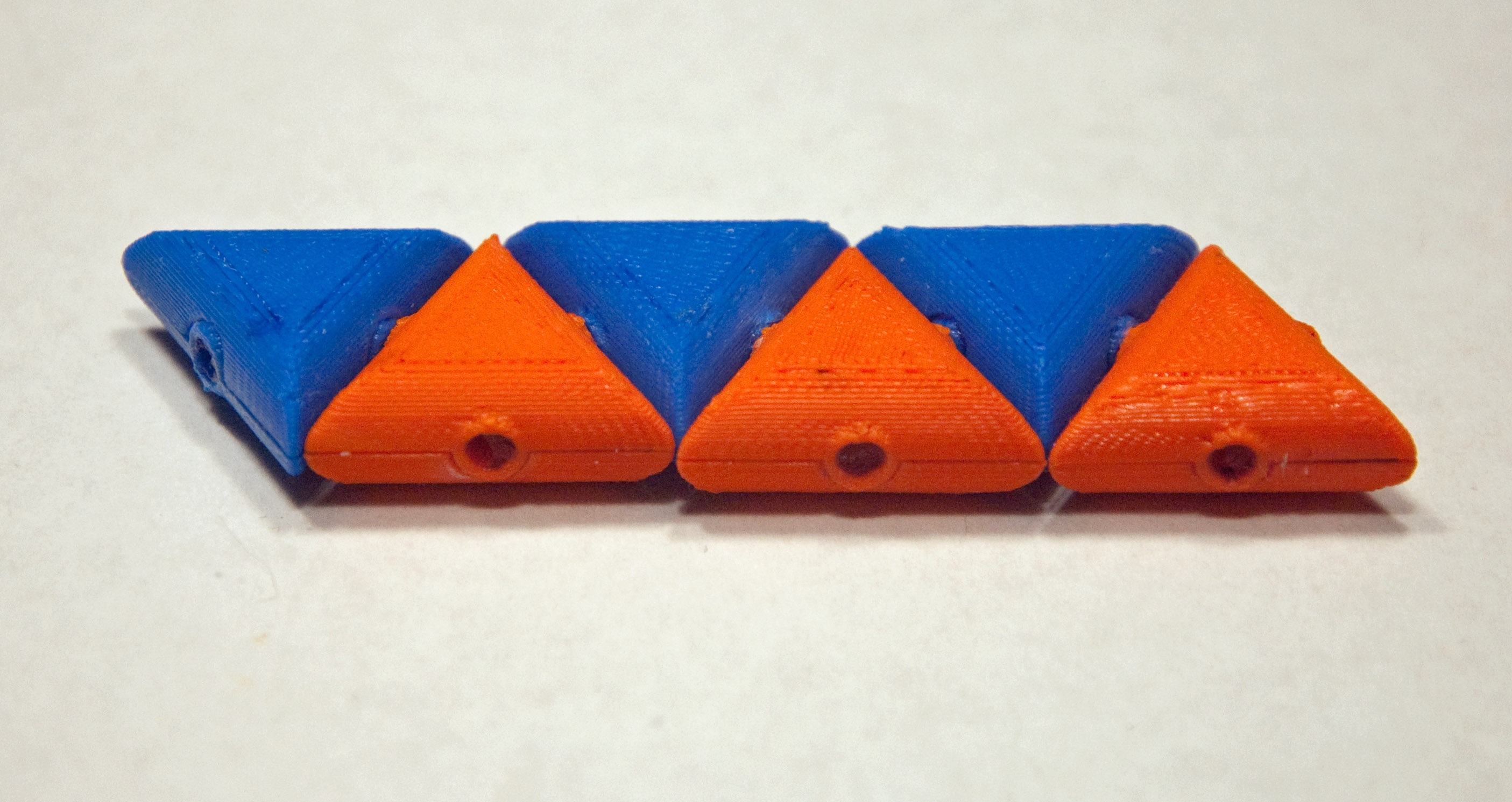
We now move to simpler triangular shapes with either all N-poles out (blue) or S-poles out (orange). So now all bonds are once again going to be equivalent (blue triangle face to orange triangle face). However, as you can see in the schematics and photos, ONLY a final hexagon will have six bonds (other variations will have only five). This means that, overall, nature should prefer the hexagonal configuration (by tending to break up the other configurations).
CAD files for shape (same as experiment #2 but 3D printing colors either both orange or both blue):
Having a little trouble finding just the right "temperature" to assemble hexagons? Maybe it's time to develop a scientific strategy. Think of this experiment in reverse: In essence, you've been trying to crystallize one structure but not another. The inverse experiment would be to try melting only one of the structures. The more stable hexagon structure should "melt" at a highest temperature. The other structure(s) should "melt" at lower temperatures. So the solution could well be to sit at a temperature under the melting point of the hexagon, but above the melting point of the other structures. Thus:
a) Assemble a hexagon by hand in the bath, then gradually increase the shaker temperature/speed until the shape just begins to break up.
b) Assemble the long bar configuration by hand, then gradually increase the shaker temperature/speed until it just begins to break up.
c) Separate all of the triangles, and turn the shaker up to a high temperature/speed. Then slowly decrease its temperature/speed to a value BETWEEN the two temperature/speeds you observed above. With a bit of patience, this should result in the assembly of a hexagon
5) The effect of reactant concentration
FOR THIS EXPERIMENT USE: 9 solid orange triangles + 9 solid blue triangles
Once you have succeeded at (or more likely given upon) the experiment 4a above, try tripling the number of triangles. This should triple the rate at which bonding occurs, which would normally also triple the risk of shapes being trapped in less desirable configurations (i.e. misbonded into "crystalline defects"). But with these simple triangles, it is very unlikely that such misbonding will occur. A more atomically accurate experiment would be a repeat of #3 (where two types of bond could form) using three times as many shapes.
6) The effect of catalysts (Under construction: Still searching more effective "catalysts" - February 2014)
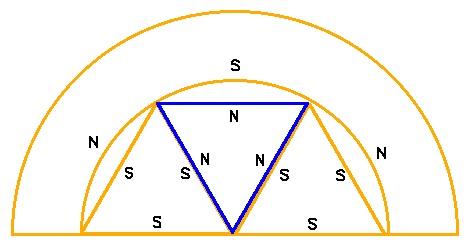
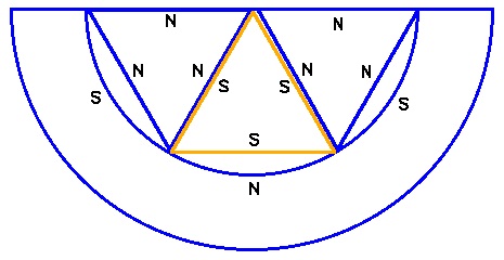
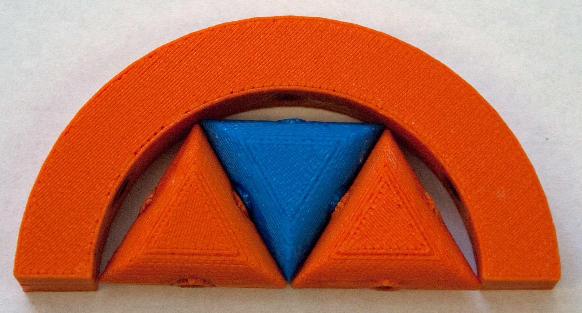
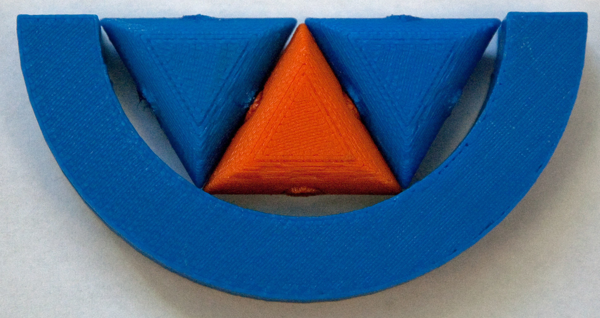
FOR THIS EXPERIMENT USE: 6 solid orange triangles + 6 solid blue triangles + 1 orange C + 1 blue C
Nature's final trick is to use catalysts or enzymes to guide the parts together into the desired configuration. By definition, the catalyst should only participate in the middle of the reaction, and then separate back out to once again stand alone. To approximate the effect of a catalyst upon the above triangular shapes, we have made C-shaped half rings. The inner edges of these C's have three magnets embedded at positions that should draw in three triangles and cause them to bond together into a half hexagon. However, given the curvature of the C, its magnets and those in the triangles will have a larger than normal separation. Thus, with a little bit of luck, once assembled, the half hexagons should vibrate loose. Simultaneously, in a second C, with complementary magnets, the other half of the hexagon should assemble to be released and bond with the first half hexagon. To better visualize this process, examine the schematics below, noting the magnet pole orientations in both C's, and how the half hexagons they assemble should then be able to bond together forming a full hexagon.