New Home of the UVA Virtual Lab:
We Can Figure This Out.org
We Can Figure This Out.org
|
|
New Home of the UVA Virtual Lab:
We Can Figure This Out.org |
|
| > WCFTO Home > Nano Home > Labs > Self-Assembly Lab |
On the class homepage, I described self-assembly as being "when we design the parts so that they know how we want them to finally come together." This is loosely correct, but it trivializes self-assembly by implying that once the parts are correctly designed and built, all we have to do is get out of the way. Nature is seldom, if ever, so accommodating. Real-world self-assembly will almost always produce many, many alternative structures. If we did our design work properly, the structure we intended has the lowest energy of these alternatives. But that does not mean that nature will home right in on this structure. Instead, via a statistical process, nature will sample all of the structures, assembling them and disassembling them. Or, even worse, it will assemble part of one structure here, and part of another structure over there. Nevertheless, under just the right conditions of temperature and reactant concentrations, our desired lowest energy configuration will be slightly more robust, and will stay together slightly longer. Then, over time, it is likely that more and more of our reactants will find their way into the configuration we intended. This delicate balance of assembly and disassembly is at the heart of all self-assembly processes, ranging from crystal growth to protein folding. And as one who spent a career trying to optimize various forms of nanoscale self-assembly, I felt that it was essential that any student lab on self-assembly not only include this balance but that it do so in a way that was clearly visible. This belief led me away from lab ideas such as chemical synthesis of gold nanoparticles (as depicted in the materials for my The Need for Self-Assembly lecture note set) because you cannot really see what is happening in chemical synthesis and must accept the suggested self-assembly mechanisms on faith. I therefore looked for macroscopic models that would clearly depict the balances of self-assembly. I was ultimately inspired by experiments developed by the University of Wisconsin's former NSF MRSEC center. They painstakingly fabricated floating magnetized shapes that served as analogs of self-assembling atoms (for more details on their work, see the Instructor's Page for this lab). Using a more modern (and much simpler) 3D printing process to fabricate our shapes, we have developed the following experiments:
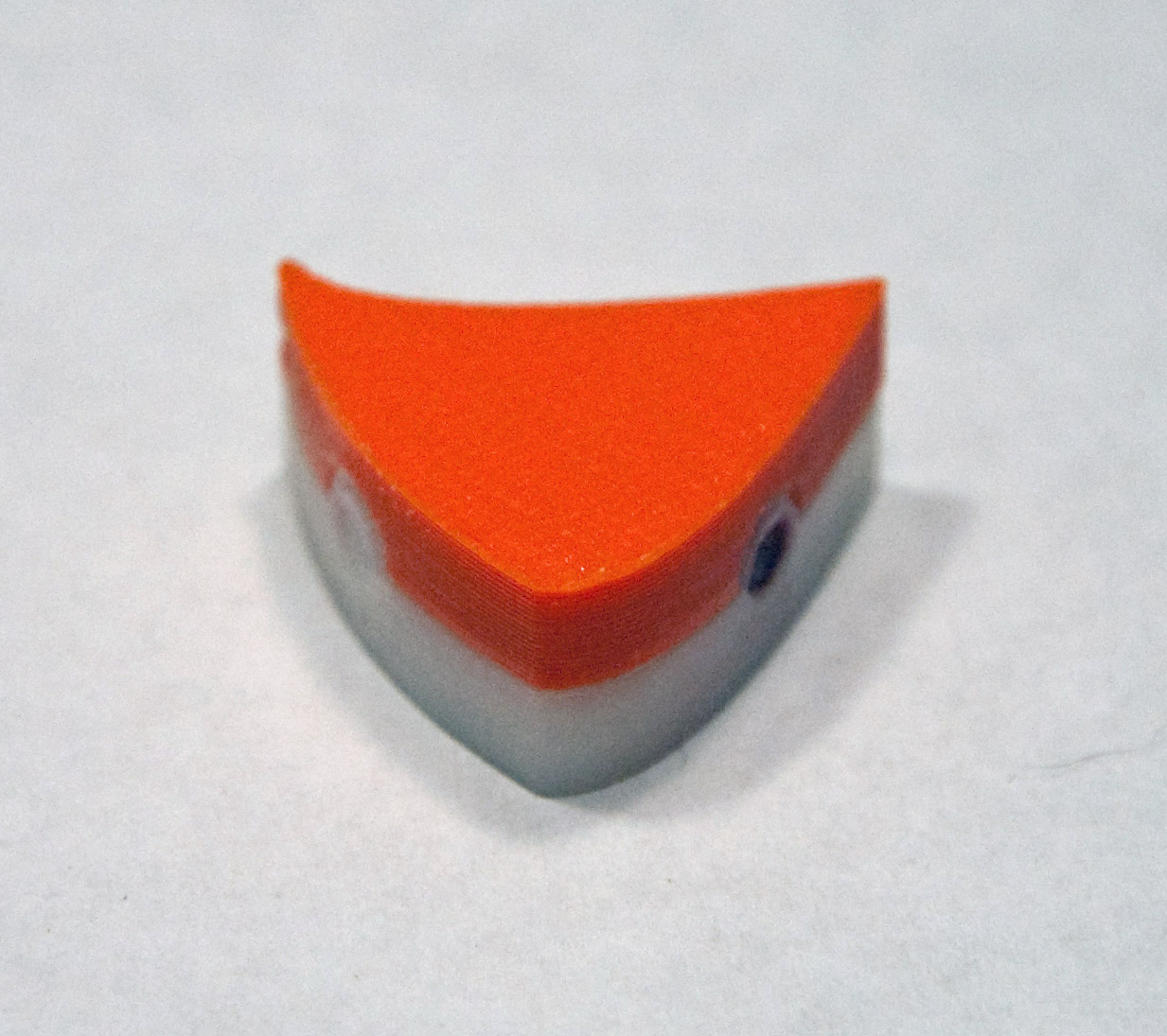
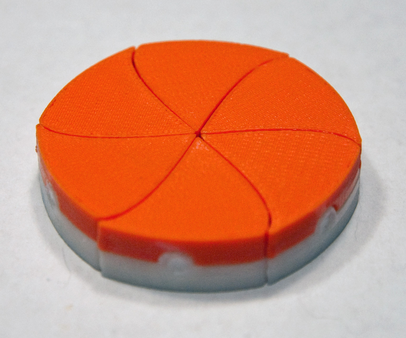
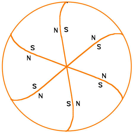
1) Idealized Self-Assembly: Parts that can ONLY come together the way we want them FOR THIS EXPERIMENT USE: 6 orange/white near triangular "pinwheel" shapes This experiment is run as a timed contest between class teams. The winning team is the first to achieve full self-assembly by controlling only the orbital shaker's rotational speed (temperature). The experiment uses triangular shapes with their faces curved so that they will only fit together tightly in the desired pinwheel shape. Tops of the shapes are orange, bottoms are white (so marked because upside down shapes would not fit together as intended). As shown in the schematic at the far right, magnets are embedded in ONLY in the shape faces that are intended to bond together:
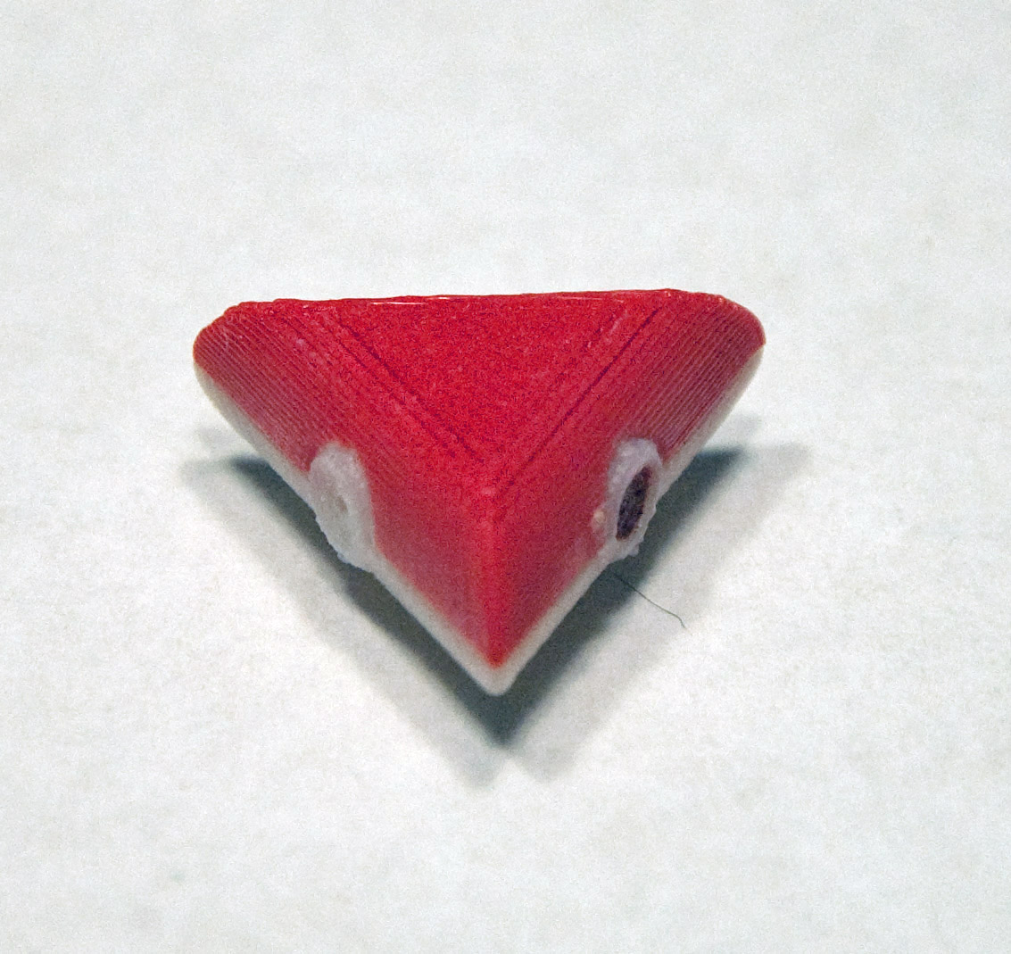
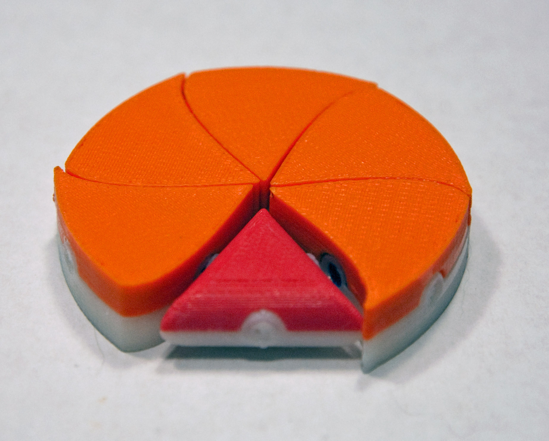
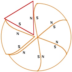
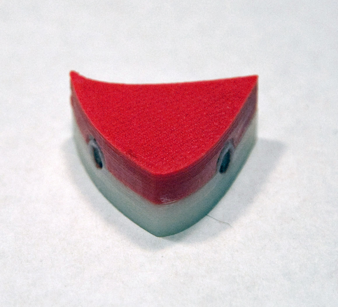
2) Slightly Non-Ideal Self-Assembly: A substitute part with not quite the right shape FOR THIS EXPERIMENT USE: 5 orange/white near triangular "pinwheel" shapes + 1 red/white triangle This experiment is again run as a timed contest between class teams. It is a variation on experiment #1 where one of the orange/white shapes is replaced by a triangle with straight sides that won't quite fit into a perfect pinwheel. As shown in the schematic at the far right, all of the shapes (new and old) still have magnets are embedded in ONLY in the shape faces that are intended to bond together:
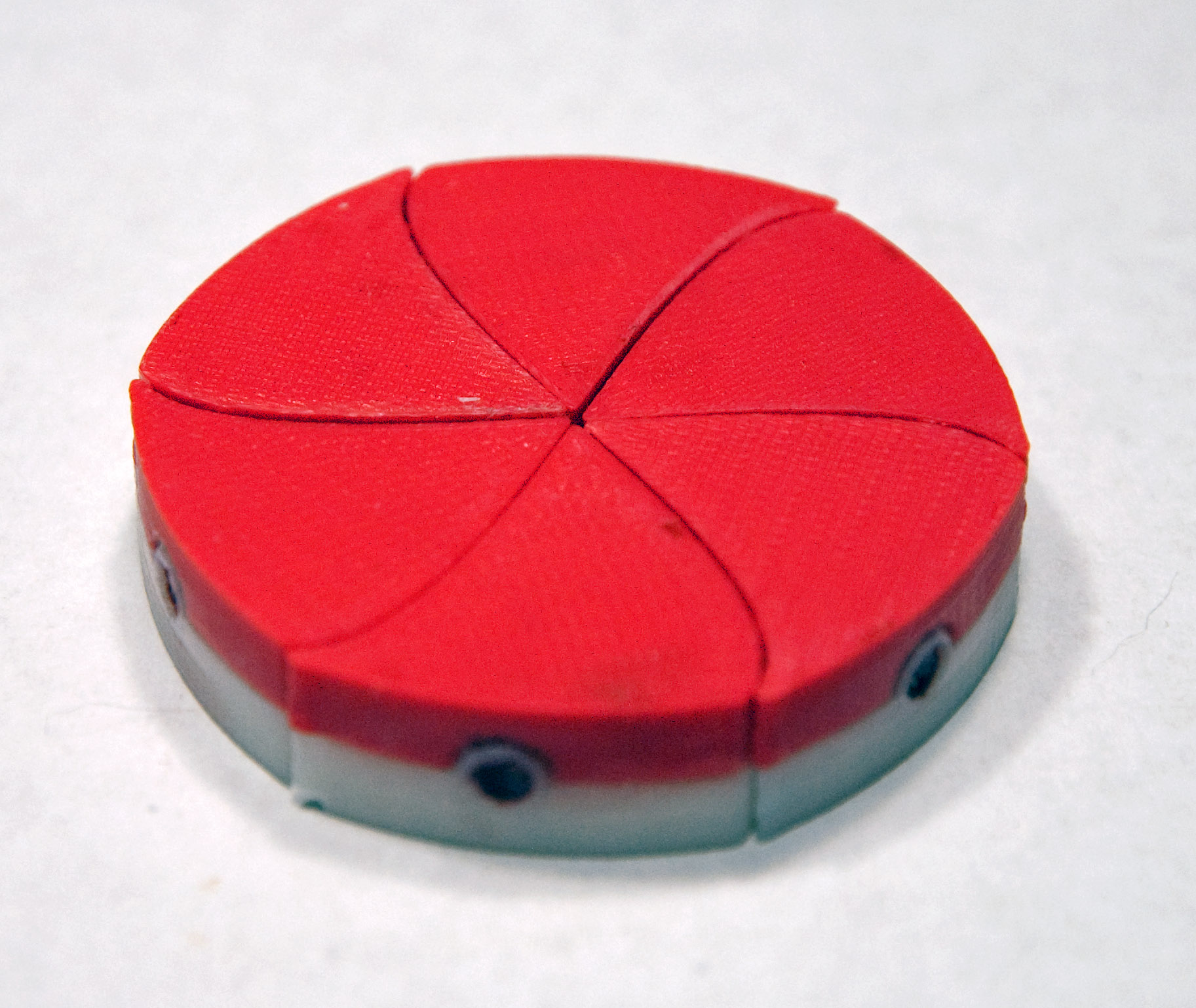
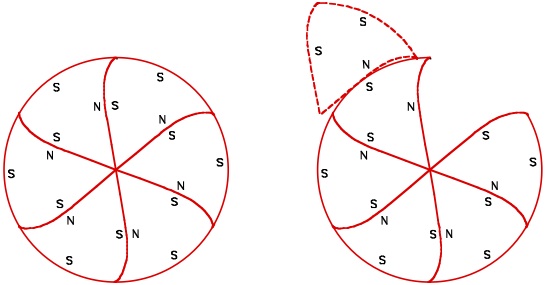
3) Realistic Self-Assembly: Parts that can fit together in more than one way FOR THIS EXPERIMENT USE: 6 red/white near triangular "pinwheel" shapes This experiment is again run as a timed contest between class teams. It resembles experiment #1 but each shape now has an added (S) third magnet. As shown in the schematic at the far right, this means that shapes can now come together in two different ways. In the new configuration the curves of the mating faces don't match precisely. As a result, this new bonding will be slightly weaker than the original more tightly fitting configuration. This represents natural self-assembly more realistically in that the "temperature" (orbital shaker speed) will have to be set so that the alternate bonding configuration is broken back up while the original bonding configuration persists.
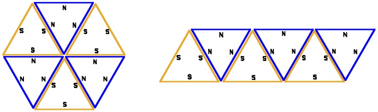
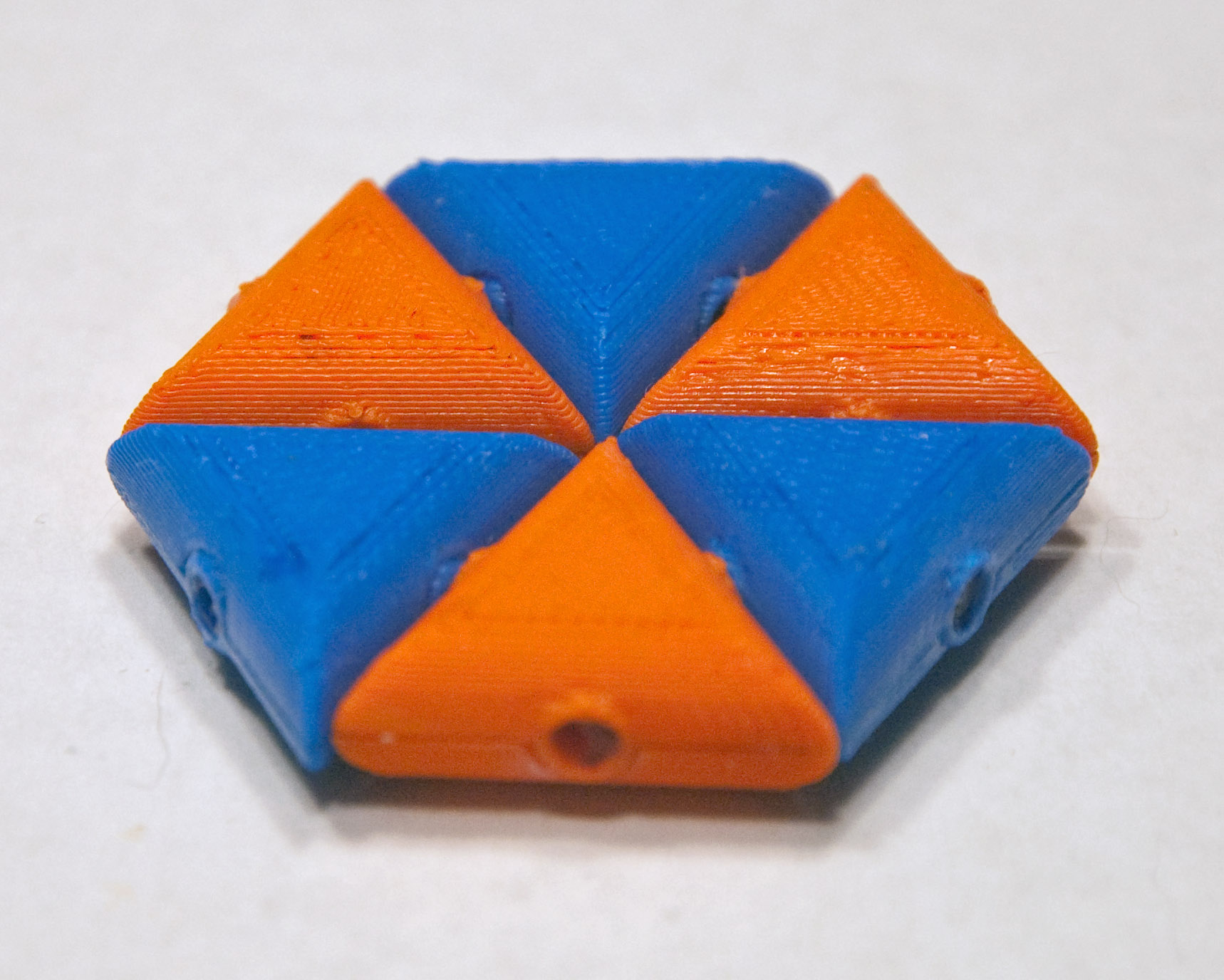
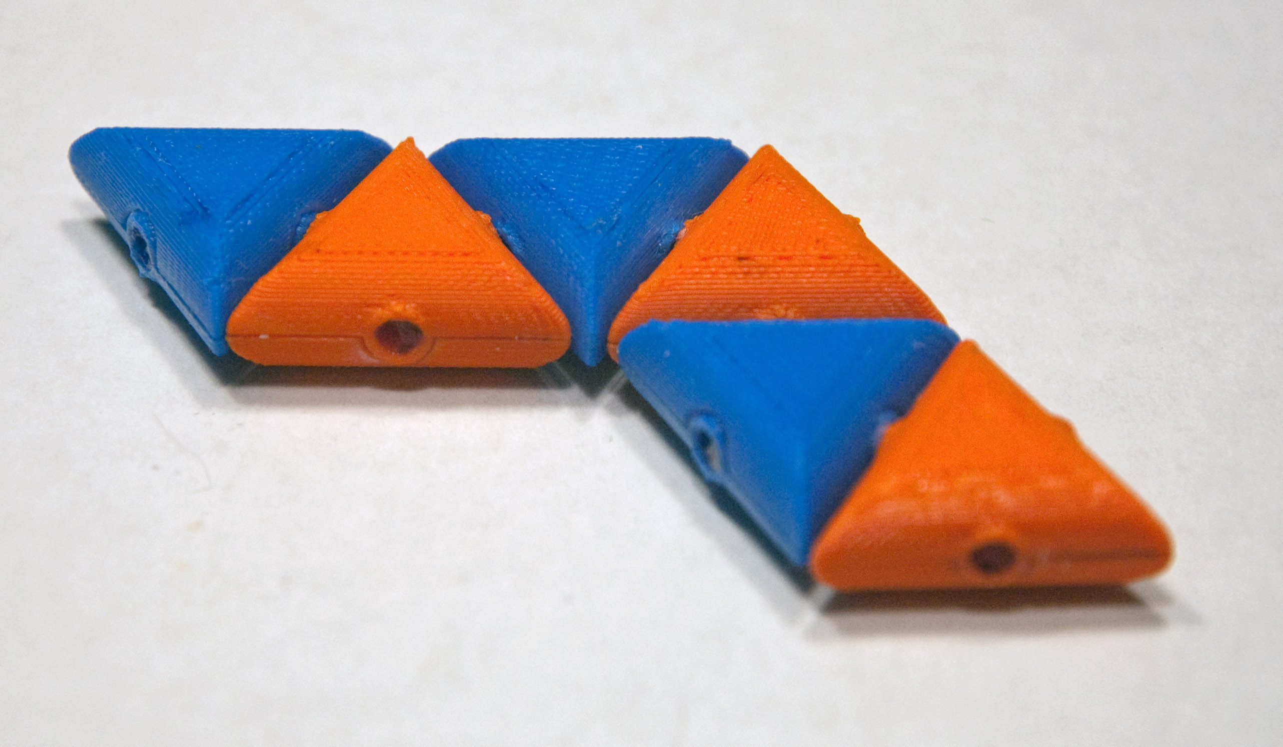
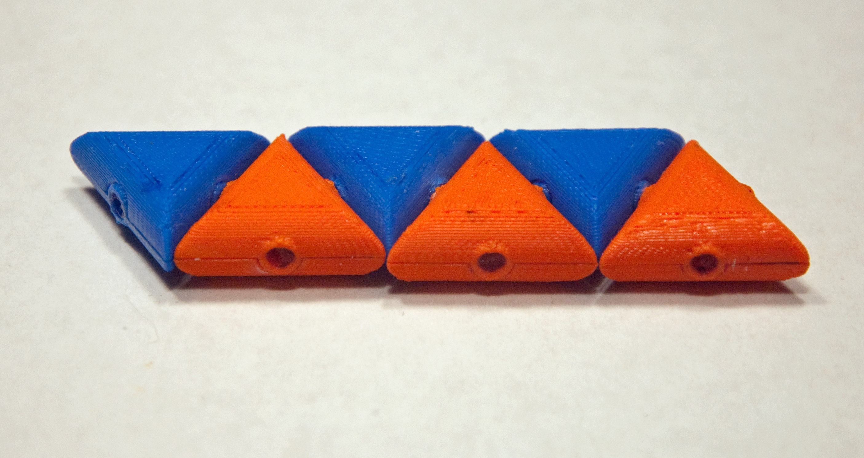
4a) Even more Realistic Self-Assembly: All bonds are equal but final configurations are not FOR THIS EXPERIMENT USE: 3 solid orange triangles + 3 solid blue triangles We now move to simpler triangular shapes with either all N-poles out (blue) or S-poles out (orange). So now all bonds are once again going to be equivalent (blue triangle face to orange triangle face). However, as you can see in the schematics and photos, ONLY a final hexagon will have six bonds (other variations will have only five). This means that, overall, nature should prefer the hexagonal configuration (by tending to break up the other configurations).
4b) Turning the preceding experiment on its head Having a little trouble finding just the right "temperature" to assemble hexagons? Maybe it's time to develop a scientific strategy. Think of this experiment in reverse: In essence, you've been trying to crystallize one structure but not another. The inverse experiment would be to try melting only one of the structures. The more stable hexagon structure should "melt" at a highest temperature. The other structure(s) should "melt" at lower temperatures. So the solution could well be to sit at a temperature under the melting point of the hexagon, but above the melting point of the other structures. Thus: a) Assemble a hexagon by hand in the bath, then gradually increase the shaker temperature/speed until the shape just begins to break up. b) Assemble the long bar configuration by hand, then gradually increase the shaker temperature/speed until it just begins to break up. c) Separate all of the triangles, and turn the shaker up to a high temperature/speed. Then slowly decrease its temperature/speed to a value BETWEEN the two temperature/speeds you observed above. With a bit of patience, this should result in the assembly of a hexagon
5) The effect of reactant concentration FOR THIS EXPERIMENT USE: 9 solid orange triangles + 9 solid blue triangles Once you have succeeded at (or more likely given upon) the experiment 4a above, try tripling the number of triangles. This should triple the rate at which bonding occurs, which would normally also triple the risk of shapes being trapped in less desirable configurations (i.e. misbonded into "crystalline defects"). But with these simple triangles, it is very unlikely that such misbonding will occur. A more atomically accurate experiment would be a repeat of #3 (where two types of bond could form) using three times as many shapes.
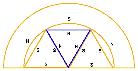
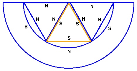
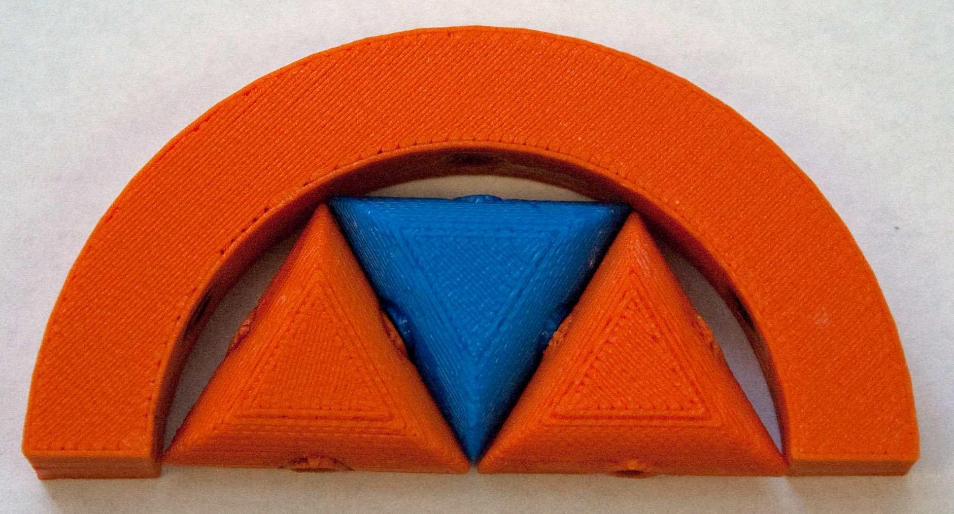
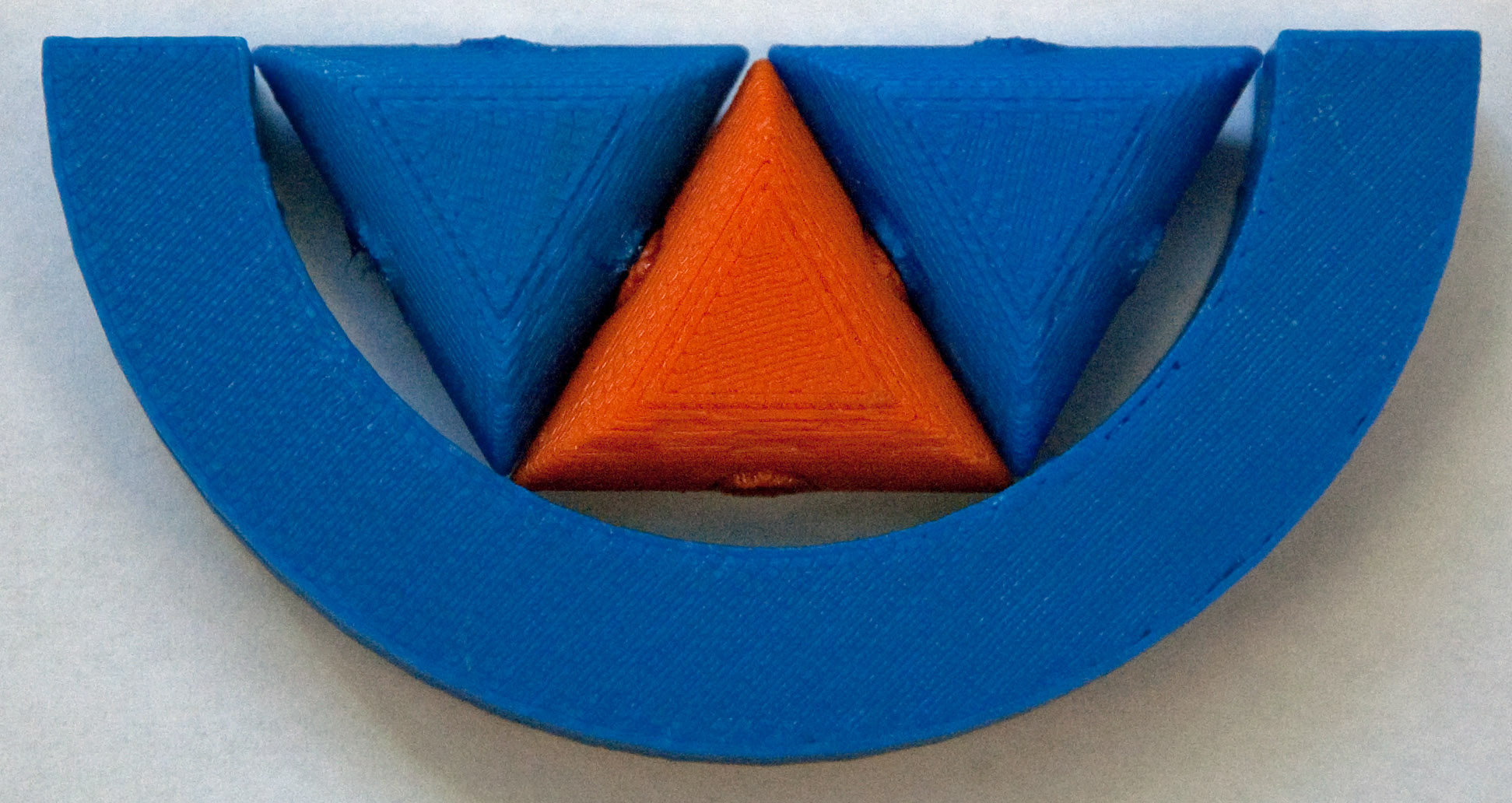
6) The effect of catalysts (Under construction: Still searching more effective "catalysts" - February 2014) FOR THIS EXPERIMENT USE: 6 solid orange triangles + 6 solid blue triangles + 1 orange C + 1 blue C Nature's final trick is to use catalysts or enzymes to guide the parts together into the desired configuration. By definition, the catalyst should only participate in the middle of the reaction, and then separate back out to once again stand alone. To approximate the effect of a catalyst upon the above triangular shapes, we have made C-shaped half rings. The inner edges of these C's have three magnets embedded at positions that should draw in three triangles and cause them to bond together into a half hexagon. However, given the curvature of the C, its magnets and those in the triangles will have a larger than normal separation. Thus, with a little bit of luck, once assembled, the half hexagons should vibrate loose. Simultaneously, in a second C, with complementary magnets, the other half of the hexagon should assemble to be released and bond with the first half hexagon. To better visualize this process, examine the schematics below, noting the magnet pole orientations in both C's, and how the half hexagons they assemble should then be able to bond together forming a full hexagon.
Copyright: John C. Bean |
|||||||||||||||||||||||||||||||||||||||||||||||||||||||||||||||||||||||||||||||||||||||||